Tuesday, 4 January 2022

Lorlie an Foster Scenery part 2

 In the last post on this I got the track changed and the elevator moved in Lorlie. The old spot now needs to be smoothed out and some holes filled. My scenery is glued  down with a mixture of Weldbond and matte Mod Podge with equal amounts of both and it is then cut 35 glue with 65 water. All I have to do to remove it is wet it down and scrape it off. I use the matte Mod Podge because it is a flat finish, if you use just Weldbond it leaves the dirt looking wet. The track is glued down with just Weldbond and never moves but again you can sook it down and you can then get the track to come off. I have just changed to a new product for scenery glue called Rheotech Mat Polymer  which comes as a matte finish and works better at holding the dirt over time.


Here is the new placement of the elevator and the siding. The scratch built loading platform is on the right of the siding. I have also added the crossing in to the industrial part of town.


Here I have added the crossing and street to the industrial side of Foster with another scratch built loading ramp in position. The tooth picks mark out each of the lots for businesses. They are standard sized lots. So there are less businesses to model and it looks better as I feel less is more. I use real dirt and screened sand. The grade up to the track is done with just sand, once you have it in place you wet it down and glue it in place. It is real easy to work with you can sand an inch deep and have no trouble glueing it. If you tried that with dirt it would never work. If I want it to be dirt I add a covering of dirt after the sand has set up. This is a real easy way to have your terrain also rise and fall or to fill holes.


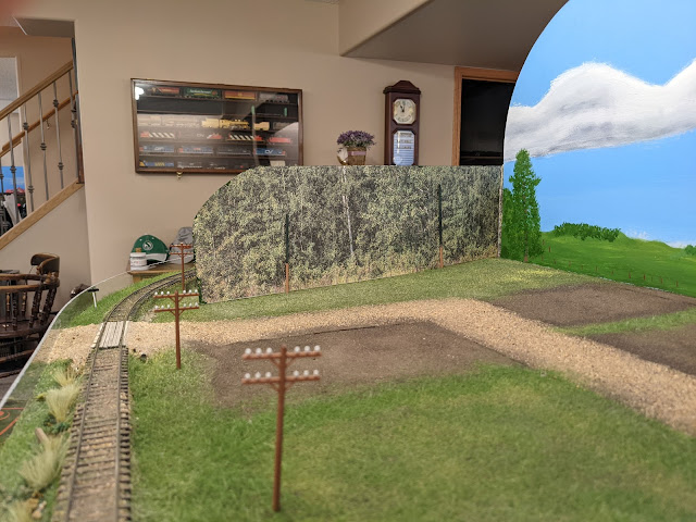
I then did the same in Lorlie. The spot that the siding and elevator used to occupy is now hidden by scenery. The sand you see in picture has been glued down to fill holes and the parts that came up when I removed the track and elevator. I will then sprinkle it with dirt. I have also installed the street and a crossing behind the locomotive and another road that leads to the Station, a loading dock and a couple more businesses. I have also added the road from the exit of the elevator. 


I then painted the back drop for Foster and added the tall grass between the lots.  The loading platform has been sceniced along with rest of the right of way.

The same has been done in Lorlie.


I have also finished painting the backdrop on the main. I added  more fencing on the right of way on the main and the track to Lorlie and Foster. The tall grass was added before the fence went in. For the page wire I used metal window screen and 6"x6" wood posts to resemble the cedar posts the railways used.


The finished painted backdrop  on the main.


I then added my view blocks to Lorlie and Foster. I took pictures of groups of trees and printed them and then glued them to card stock  adding trees in front of them. The view blocks do not photograph well as the colour doesn't come through but they are green trees. The sticks just hold it in place.


This is the view block next to the main line. The leaves on these trees are a dark green but show up light in the photograph.


I then went and finished painting the backdrop in Atwater behind the elevators.


Monday, 25 October 2021

Buying/Getting My Laser

 I have just bought a Full Spectrum Muse Core laser. I will take you through the process of picking this machine and the criteria I used. The first few days I had it were a bit overwhelming and I will explain some of the help I received to get it up and running.

The tube on the wall behind the laser has nothing to do with the laser per se - it is the vacuum header for the whole work bench. The shop vac is on the floor at the end of the bench.


 I already had the ability to run an Epilog Fusion so I understood a lot about laser capabilities. Having said that I still learned many things while researching this brand. I did not want a Chinese  machine that you would have to do a lot of tinkering with to get it to run even if it was cheaper. I would have liked to support a Company with Canadian offices but that would have limited the choices to just Epilog and Dremel. You may see a Canadian presence but the more you research it you see they are supported from the USA. I also knew that turning it into a business was not my top priority. I did consider how it would handle work if I started to do business work with it. I spent 8 months from when I started thinking/researching until I made a purchase. When you look at reviews for this company there will be noted differences if the review was made before 2019 as there was some company changes made after that time. I then found a You Tube channel called Steve Makes Everything.  You really, really need to go and watch his videos especially if you have not run a laser before. He has a lot of excellent information and I was able to Zoom with him. He was nice enough to do a cut for me of a diamond harrow in HO scale. This was my test against this machine and the Epilog. The dimensions in the drawing below are 1:1 so divide by 1:87 to see how small it is when cut.


These were cut on the Epilog


These were cut on the FSL that Steve did for me.  I had told him it could be quick and dirty. I am happy with how well the FSL cut them. These are the tiniest thing he has cut. He said he could have done better if he had aligned his machine first.


Companies

 -FSL  Full Spectrum Laser

-Glowforge

-Boss

-Thunder 

-Dremel

-Epilog Fusion very nice very expensive

Criteria

-price <$6,000

-what options I really needed, camera, rotary attachment could they be added after. So I can get the riser and the rotary attachment, different length lenses. I can't add the camera in the future but I just didn't think I would get enough bang for the buck considering I am not going straight into business.  

-after purchase support I guess time will tell but Steve has been happy the couple of times he needed support. There are tons of reviews on all the brands but it not easy to tell just from this.

-operating system they all have something different so you have to look at them all to see which ones you think you would like. The Glowforge is 'cloud based' so all your work lives on their server. If it gets busy you may not be able to print a job until you move up the que They have a fix for this but it is a yearly fee.

-file formats that can be used now most operating systems will accept a lot of file formats but you should make sure they have the ones you need. 

-bed size and depth you will see in the chart that some have more depth than others or like the FSL you add an extension to the base to cut bigger material. Some have smaller and larger bed sizes.

-actual machine size I have a somewhat limited space in the garage where I want to put the laser so it was also a consideration

-weight as you will see in the chart, there is quite a difference in weight but I really wanted something 2 people could move easy like 50lbs not 250lbs

-replacement laser tube cost this can also vary a lot. The Glowforge is expensive because you have to send the whole machine back to Washington to get a laser tube replaced.  Not convenient from Canada.

-owner manuals for just about all my purchases I like to read the owners manual before I buy them.  I do not rely on the sales pitch that may glaze over important info. 

Here is the link to the table I created Table Comparison.  The Muse 2D is in red because just as I had decided to pick this it was no longer being sold. ARRR! So I moved down in price to the Basic, always good to save more money.


Getting Set Up

I waited until it was shipped to see exactly how it would fit on the bench. Once I had it all unboxed I placed it on my bench. My bench is 24" wide and I also needed to see where the vent would go. I added 2 - 2x4's to the front of the bench to make it wider and drilled the 4" hole for the vent line to the outside.  In the future I might add another 2x4 to make that portion of the bench wider yet. I also had to get new stands for my bench grinder and my vise as I have run out of room on the bench. My lathe sits to the right of the laser under the towel. There will also be a towel to go over the laser to keep it clean. The garage in the winter is kept between 12-14C. 14C if I am going to be out there for a long time. I also bought a jug of Ethaline Glycol to mix with the distilled water that is in the Cool Box (on the left side of the laser) for cooling the laser tube. I mixed this so it is good to -25C  just in case the power goes out or if the furnace quit because the laser tube is glass and can't be frozen.

 I was finally ready to turn it on. I connected it to my WIFI network and then connected it through Google on my laptop so that I could ensure I had the operating program functioning. Next was to run a test to check the mirror alignment. It was not aligned so I had to go through the procedure to realign the mirrors. This problem can  occur due to rough handling during shipping. I didn't think the procedure looked too hard but it turned out to be a little difficult. It took me 3 tries to get it right and I had to bring in Brian to ensure I was not missing anything. I had run out of the thermal paper required during this test as they do not send much with the machine. I then had to wait a couple of days for that to come, but now I have enough for life for $20. I also bought a 3" mirror that can stand up on the bed so I can see the burn marks on the paper easier and cut a piece of card stock so as to block the red beam indicator if needed so I can see the burn marks better also. It will be easier from here on in now that I have these tools and understand the process better.  All lasers need this mirror adjustment completed from time to time. I then had to align the gantry as it was out by .5" on one side, easy enough to do. FSL has videos that show how to align the mirrors and gantry. This all took me a week but I had other things to do like baby sitting, pickleball, a couple of Zoom meetings and getting ready for winter. I knew when I ordered it that I would not be cutting the day it arrived. HAHA πŸ˜‰ but now I am ready to run a project. This will be covered in my next post.

Note:  When I was setting up the laser I was keeping things neat using zip ties to tie up cords. I also shortened the water line hoses that go between the laser and the Cool Box which made sense at the time. The part I missed was when I need to drain the water system my hoses will be a little short to drain to a pail. Have to resolve this at some point but not right now.


Tuesday, 25 May 2021

Lorlie and Foster Scenery Part 1


This portion of the layout has looked like this for a few years and has been used as a place to pile stuff on???  It's time has come. I will do a couple of posts on this area. I knew I wanted to make changes to the layout of the track work but just could not get motivated. I find it really hard to fit square pegs in to round holes. When it moves me it goes really easy and I can find my artistic side and enjoy it.

So the first task was to change the the direction of the siding at Lorlie.  Prior to this change the sidings at Lorlie and Foster faced opposite directions. I moved the switch from the right side of the picture to  the space on the left side. The elevator will also need to be moved. Since I glue my track down with Weldbond white glue I just had to wet it and then pry out the switch. The switch is laying at the back in 2 pieces, I then took out the ties on the left for the switch to go back in. Because the track is on a curve it worked out that I could reuse the same switch by having the divergent become the main line and I was also able to use some of the same rail .


This picture shows the siding rails and ties have been removed.


The photo below shows the switch stand and new siding in place and rails back on the main line. The main is code 70 and the siding is code 55. The wiring and controller for the switch is complete. I also made new points for the switch.


With the switch and siding changed (The following procedure for texture is what I use everywhere) I  ballasted the main from Lorlie down to Foster. I used screened sand for the ballast. Once the ballast is in place I spray it with ( 10%  of  70% alcohol + 90% water) Once wet I dribble on the glue. I used my card stock E Class station to see exactly where it will sit and have laid down some boards where the crossing will go. I also added the dirt to the outside of the right of way. 


The white you see in the dirt in any of the next pictures is just glue (30% Mod Podge matt and 20% Weldbond glue). I use the Mod Podge to make the glue a matt finish so the dirt is not glossy when it dries which is what would happen if I just used Weldbond. I add the Weldbond to the mix to give it more strength. If you want wet looking dirt then just use the Weldbond. The surface of the foam has been painted a clay colour so if some dirt comes off that is what you would see. It also gives slopes a clay colour that I can blend in to the dirt. The ditches were cut using a cone wire brush on my drill or with a counter sink bit to cut the smaller ones or deeper spots. The bottle you see is my glue applicator. I dribble on the glue and spread it with my fingers or with a brush. The screened dirt is then sprinkled on top of the glue. At this point not all the dirt may stick but that is ok as I will add more glue to add the grass.


This is my dirt applicator by using this I can control it better and have a tighter edge. I also have a small version of this for tight spots or against walls. The screen has about .015 openings.


Coffee time.


Looking at the middle of the picture below around the outside edges of the dirt there was a change of height from where the pieces of foam meet. To create the transition I tape the joint first with masking tape and then add very fine sand, wet it and glue it. While it is wet I sprinkle dirt on top of the sand. The reason for this is that sand  is very easy to work with even if it is an inch deep or more.  When the glue dries the sand is very solid. If I tried the same thing with dirt it would be hard to ever get it wet enough so that when you add the glue it doesn't ball up and run and deeper applications of dirt will crack as it dries but the sand never does this. The dirt has also been added to the rest of the inside of the curve. I use this same technique to make my road crossings.


Once the dirt is down I wet it again, dribble on more glue and add the grasses. I use Woodlands fine foam and Noch static grass. The grass on the inside of the track only goes as far as the right of way would be. It will be taller and thicker where the fence line is. 


These are the shaker jars that I use to apply ground fine foam. They are just old  jars with holes punched in the lid. Green and burnt green are my base colours.


To get the static grass to build up a bit I will spray the first coat with cheap high hold hair spray and then apply some more. The 2 bottles on the right now just have my wettings agent in them.


I then use any of the other  ground foams I have depending on what look I want.


Since I ran out of Real Water I have started using white glue for wet spots. At the bottom of the picture below the ditch in this case was filled with undiluted white glue.   After it is partly set up I added the tall grass, ties and some more rocks. The white glue depth will shrink so you may have to add a second coat to the desired depth.


I also added this pond at the end of the track at Foster. This track was used to go back to the main line but I removed that connection so it is just a dead end branch line now. There will be a tree view block added later.


This shows another place where I used sand to make the transition from the 1 inch high foam before the dirt is added.


This brings us all the way back to Waldron


The picture below shows the view of the round pond surrounded by grass next to the partition from the Lorlie side.  You can also see that I have  added more dirt. There will also be a tree view block on this side.


The elevator has been successfully removed from its previous spot and is sitting where it will now live. The siding is ballasted with cinders. I need to add foam to fill in the holes where the elevator foundation sat  before.  Any of the texture seen on the foam where the elevator sat can be wet down and easily scraped  off. 


As seen on the left of the photo below I used pieces of foam to get the station and platform to the right height.  I glued 3 pieces of 1 inch foam together and then cut it on my band saw in to 1/16 and 1/8 thick strips. These are glued down and  the station then sits on top of the foam pieces.


The space on the curve will be a farm yard with a tree block on both sides of the divider.


Next the streets and businesses will get laid out and added for both towns. The work seen in this post   took about 6 rainy days off and on.


Tuesday, 23 March 2021

Farm Details Cocksutt 18' discer


 This is a scratch built Cockshutt 18' discer seeder a replica of the one we used when I farmed. Discers were made by many companies. Bill is using this to do summer fallow. A discer with a seed box is something that is not likely to ever be mass produced as a model. I have never even seen one in 1/64 by Ertl.   They were used for seeding on the prairies until the 70's when drills made a comeback. You will see older models of these with or without a seed box and you may see them referred to as "one-way". This is because you can only go one way around the field with them in a counter clockwise direction. The discer does not turn very sharp to the right at all and you can not back up with it. This discer would require about 80HP to pull. They could  be hooked together to make them as long as you would need. The actual width of cut is always less than the length because of the angle they pull at. 

One of the hardest things in this build was finding the disc blades. They had a 6" spacing so I would need 16 of them. The next hardest thing to find was proper tires (which are now available at Shapeways). I drew it out in CAD from memory referencing a couple of pictures that I have. The two 9' grain/fertilizer boxes were built from .01 styrene sheet and the ends were built from .02 styrene. I also cut 2 extra ends and sanded them down so they would fit inside and then wrapped the .01 around these and glued them together. The lid on the top was then made. This lid would have opened tilting up from the back. With the box done I then laid out the frame and made supports for the boxes to sit on. The   disc gangs were next  and after a few attempts I decided to make them from .01 styrene using a leather hole punch which left the 16" discs  slightly dished out looking quite realistic . The discs were then drilled in the center and were mounted to an .02 wire. Supports were also added between the blades to mount it to the frame. There were 6 gangs each being 3' long. After the gangs were on I added the walkway on the back. As I explained in my garbage can post there were a couple of boxes and a couple of gangs that ended up in the bin!  The T bar on the front wheel sets the height of that end of the discer and depends on the depth of the furrow.  The angle of the discer cut can be changed by adjusting the hitch. I also added a hydraulic cylinder and the hose that goes back to the tractor. The drive that turns the seed wheels inside the cups sits under the box and  is driven from the land wheel, which is the wheel on the front right side. I did not model the feed tubes that run from the bottom of the box back to each disc blade. I had some Cockshutt logo decals made for the ends of the boxes The total weight of this model is only 0.1oz. It was a very challenging build but I like how it turned out.


Farm Details Grain auger

I needed a grain auger for this scene and since you can't buy one I had to build one. This is a Sakundiak PTO drive 6" 33' which was manufactured in Regina Sask. It may be just outside of my 1959 cut off date but I was confident that most people would not realize that. I drew it up in CAD to have something to work from. To start with the frame would not support the auger when built to scale.   On the real auger this was 2x2" angle so I had to go to 3x3" and add wire in the angle.  It is still a little wobbly but it works.  This model is capable of sliding up and down to change the height if needed. The next difficulty was the exposed flighting at the bottom of the auger and I ended  up using  a small screw with coarse enough threads and some precise filing to produce the desired look .  I had to cut a few pullies before getting something I was happy with. They were then added along with a belt, The PTO shaft was added so it could be run from the tractor. The removable hopper on the end for truck unloading was made from some scrap .01 styrene. The tires and rims are from Hot Wheels because at the time I could not find any that would be correct. Now you can buy them on Shapeways or I could make some on my lathe. I intend to build a Mayrath auger  as I have found something that resembles a Briggs & Stratton motor. I already have the CAD drawing done for this auger. You could also have a gas or electric motor drive the auger. It would be able to reach the Rosco bin next to it. I will cover this topic in a second post.


The Cad drawing for this auger. Those are 16" cultivator shoves at the bottom


Monday, 22 March 2021

120' Flat Car Load


This is my 120' long test load for flatcars. It only took a few tries to get it to work. The piece is 1" x 1/4" basswood. I ran it a couple of times to see where I wanted it to sit, then I drilled holes in the flatcar decks and inserted a .06 styrene rod with about  3/8" sticking out. I then drilled the 2 holes in the piece of wood and gave it a test run. It crashed on the first 36" curve it came to so I added washers between the wood and the cars on the pins to raise it up so it cleared the deck of the middle car. I ran it again and it still crashed on the curve. I made the hole in the wood a little bigger and it made it through the first curve and crashed on the 2nd 30" tighter curve. I noticed at this point that the couplers on the cars were binding causing the cars to come off the track and tip over. I also noticed that there was no slack in the couplers. So I measured the amount of slack between a set of couplers. So to fix this I put the wood in my lathe and milled a slot extending from the holes to the middle of the car plus an extra .01" long. This allows the cars to have all the slack between the couplers. You would just make the slot longer if you had another idler car. 

This shows the milled slot in the load

I ran it again and it went all the way around on the main line with no problems. Next trial was in the yard and it ran with no problems on the ladders or any of the other tracks. The tightest curve I have is 24" and it also ran through that. The wood never tips over and rides very well. With the 1/4" thick wood it just come to the edge of center flat car which is only 9' wide. In order to have the same over hang as my passenger cars I can maybe go to to a load that  is 3/4" wide. The next step is to make a real load and the supports to support the load with the slots milled in them. The hole in the wood and the slots will only need to be .080 for it to work. The pins only extend through the plastic deck and can be removed so you are only left with a .06" hole.  This can be easily disguised if you are going to use the cars for other loads.

This picture shows the pins in the flat car deck and washers.


Friday, 26 February 2021

Farm Details Fuel tanks


 This is a 500 gal fuel tank I built out of styrene and a piece of tube. The paint job is better than it looks. I am zoomed in really tight so you can see the Gulf decal on the end. It is very delicate and only weighs <.00 oz. this is as low as my scale goes. I drew it out in Cad, printed it and used the drawing as a template to build the frame. There is intentionally no ladder as the fuel agent usually had their own. There would be a clear hose on the other end that showed how much was in the tank. I can remember when someone came to steal gas at about 05:00 and cut the nozzle off the end of the hose. My dad let the dog out and they took off. It was a few minutes before he went down there and gas was running full out the end of the hose!!!@@@??? In the end we lost 1/2 a tank of fuel. When I build another one I will just cut the frame out on the laser which will be much easier and stronger.


OK so I can't find my model but it looks just as good LOL
This is a 100 gal slip tank that I build back when I was first learning CAD. The pattern of the drawing was useful for cutting out the curved ends. I did some and filing and I then glued the ends to and .04 floor and then glued on .01 styrene to the finish it. The filler opening was then added.

Saturday, 5 December 2020

Finding really small parts you have dropped


Thought I would share this as I just had to use it to find a small #0-90 screw. Have you ever dropped that really small part on the floor which may have carpet. You can run your hand over the floor but you never really know where it boused to. This is an easy fix to that problem. Get out your vacuum and the little brush attachment. You will also need to by a pair of womens nylon socks. Do not steal one from your other πŸ˜ but you can find the backer for her ear ring😎. Take the sock and stuff it into the end of the hose, leaving an inch or more over the outside of the hose. then attach the small brush to the end of the hose over the nylon you left out. Now you can start to vacuum and the nylon will let enough air to pass through but will catch the smallest of parts. Once you have gone over the area where you think the part might be remove the brush and pull the sock out and turn it inside out and dump it on a smooth surface and did through the lint and other piese that were down there also. Repeat if necessary on a different area if you did not find the part


Friday, 4 December 2020

Modeling and the garbage can


What do I mean by the title of this post? Well the simplest explanation is that not everything you build or try will make it to the layout the way you want it. I have always liked new technologies, materials, construction methods and being as close to scale as is reasonable. The problem with this is that the more new things that you try the more likely it is that those items will end up in the garbage until you get them figured out. Now this mostly applies to things you are building from scratch. When I was designing/building the roof on the dormer for the E Class station there were at least 5 that went to the garbage before I got it right. The first outhouse I built went to the garbage with force as I could not keep it straight and it was one of those times when glue would just not hold. I spent 3 years trying to build/design a table auger for a combine, there were at least 6 of those that went in the can as well. When I built the discer there were 2 of those that went to the can. One because of design flaws and the second because I crushed it in near the end of the build. Most of the things that I design now are cut on the laser and  is all done in .04-.06 card stock first so that I can test it out and make changes to the CAD drawings then cut it again!  I repeat this until I am happy and unless I am happy with these items they all go to the garbage. Once I like it then it gets the final cut. Even some final pieces go to the garbage because I forgot to turn off the text layer and now there is a lasered number 6 or 3 or the word roof cut in the part. LOL  LOL  I could go on and on but you get the point. Right now I am in the design phase of 3 CN depressed center flat cars. Since I have only GA's for a couple of the cars and only 1 picture of each car there are more than a few things to ponder. One car is a  42' with two 2 axel trucks. The next is a 60' with two 3 axel trucks and the last one is  a 67' with four 2 axel trucks. I drew these at the lake when it was raining and there are alot of similar parts so I just did all 3 at once. I am also working on a 36' CN well hole flat car.  These are all getting some parts cut so that I can start to test how well they will run, assess whether the structure is sound and see if there is the correct amount  of clearance for the depressed cars. As with many of my projects I know  that some parts will not work because they do not have the integrity in HO but I am fine with that. I am also getting the sand paper cut for the stucco for E Class stations and I will test it on the card stock model I still have from the first build. I also have a GTP B Class station that  cuts will be done  for a test model. I am certain at least one roof will go in the garbage.

From this I have gained a lot of skills which have made me a better builder and raised my confidence. It also means that if I make a mistake on a kit I can usually fix it. It gives me the opportunity to have many models that you could never buy. Like my father in law would say... the sign of a good finish carpenter is to be able to hide or fix his mistakes. So don't let fear hold you back and use that garbage can.


Sunday, 11 October 2020

JMRI Decoder Pro

There may be some other tools inside of JMRI that can be debated as to whether you like them or not....but this one is just a must use. Once you have all your engines in this you can throw out the book of notes that you have as this is just to easy. You will need an interface between your computer and the layout. My layout is run with Digitrax and my interface is RR-Cirkits Loco Buffer USB. This plugs in to one of the ports on a UP5 and into a USB port on my computer.
 You will also need something that will boost the power to your programing track to enable it to read all new sound decoders. I use DCC Specialties PowerPax. You need this or one like it even if you are not going to use JMRI because sound decoders need more power to read right. If you can't read a decoder this is most likely why.   


The Decoder Pro interface uses plain english and visual not CV numbers. This never used to be an issue but now with so many options in sound decoders it really shines. Once all the info is saved for an engine you can copy it to another engine or reinstall it especially helpful if your decoder has a hiccup and loses some of it's settings. It also makes setting up speed tables much much easier. When I am going to fix a decoder problem for someone the first thing I do is read the whole decoder. I also do this with all my new decoders and any used ones that I buy. This way I get to see what is really on the decoder. If the decoder has lost its address or I am adding a new or changed address I will do this while it is on the programing track. Then I will put it on the layout and do the rest of the programming on the main because I can see the change as soon as I enter it. 
Guys will tell me what CV numbers they have changed or what new inputs they did. They may as well be speaking a different language as I do not understand what the numbers mean because I am used to just reading what the description is in Decoder Pro.
If you have not used it you should at the very least have someone show it to you. The PowerPax only costs around $60 US and the Loco Buffer USB costs around $62 US.
There are different products out there that you can use for interface and as a booster these are just the ones that I bought back in 2010 and they they are still available.
The Loco Buffer also gives you the ability to connect to Engine Driver or WiThrottle through JMRI using WiThrottle window.