Tuesday 23 March 2021

Farm Details Cocksutt 18' discer


 This is a scratch built Cockshutt 18' discer seeder a replica of the one we used when I farmed. Discers were made by many companies. Bill is using this to do summer fallow. A discer with a seed box is something that is not likely to ever be mass produced as a model. I have never even seen one in 1/64 by Ertl.   They were used for seeding on the prairies until the 70's when drills made a comeback. You will see older models of these with or without a seed box and you may see them referred to as "one-way". This is because you can only go one way around the field with them in a counter clockwise direction. The discer does not turn very sharp to the right at all and you can not back up with it. This discer would require about 80HP to pull. They could  be hooked together to make them as long as you would need. The actual width of cut is always less than the length because of the angle they pull at. 

One of the hardest things in this build was finding the disc blades. They had a 6" spacing so I would need 16 of them. The next hardest thing to find was proper tires (which are now available at Shapeways). I drew it out in CAD from memory referencing a couple of pictures that I have. The two 9' grain/fertilizer boxes were built from .01 styrene sheet and the ends were built from .02 styrene. I also cut 2 extra ends and sanded them down so they would fit inside and then wrapped the .01 around these and glued them together. The lid on the top was then made. This lid would have opened tilting up from the back. With the box done I then laid out the frame and made supports for the boxes to sit on. The   disc gangs were next  and after a few attempts I decided to make them from .01 styrene using a leather hole punch which left the 16" discs  slightly dished out looking quite realistic . The discs were then drilled in the center and were mounted to an .02 wire. Supports were also added between the blades to mount it to the frame. There were 6 gangs each being 3' long. After the gangs were on I added the walkway on the back. As I explained in my garbage can post there were a couple of boxes and a couple of gangs that ended up in the bin!  The T bar on the front wheel sets the height of that end of the discer and depends on the depth of the furrow.  The angle of the discer cut can be changed by adjusting the hitch. I also added a hydraulic cylinder and the hose that goes back to the tractor. The drive that turns the seed wheels inside the cups sits under the box and  is driven from the land wheel, which is the wheel on the front right side. I did not model the feed tubes that run from the bottom of the box back to each disc blade. I had some Cockshutt logo decals made for the ends of the boxes The total weight of this model is only 0.1oz. It was a very challenging build but I like how it turned out.


Farm Details Grain auger

I needed a grain auger for this scene and since you can't buy one I had to build one. This is a Sakundiak PTO drive 6" 33' which was manufactured in Regina Sask. It may be just outside of my 1959 cut off date but I was confident that most people would not realize that. I drew it up in CAD to have something to work from. To start with the frame would not support the auger when built to scale.   On the real auger this was 2x2" angle so I had to go to 3x3" and add wire in the angle.  It is still a little wobbly but it works.  This model is capable of sliding up and down to change the height if needed. The next difficulty was the exposed flighting at the bottom of the auger and I ended  up using  a small screw with coarse enough threads and some precise filing to produce the desired look .  I had to cut a few pullies before getting something I was happy with. They were then added along with a belt, The PTO shaft was added so it could be run from the tractor. The removable hopper on the end for truck unloading was made from some scrap .01 styrene. The tires and rims are from Hot Wheels because at the time I could not find any that would be correct. Now you can buy them on Shapeways or I could make some on my lathe. I intend to build a Mayrath auger  as I have found something that resembles a Briggs & Stratton motor. I already have the CAD drawing done for this auger. You could also have a gas or electric motor drive the auger. It would be able to reach the Rosco bin next to it. I will cover this topic in a second post.


The Cad drawing for this auger. Those are 16" cultivator shoves at the bottom


Monday 22 March 2021

120' Flat Car Load


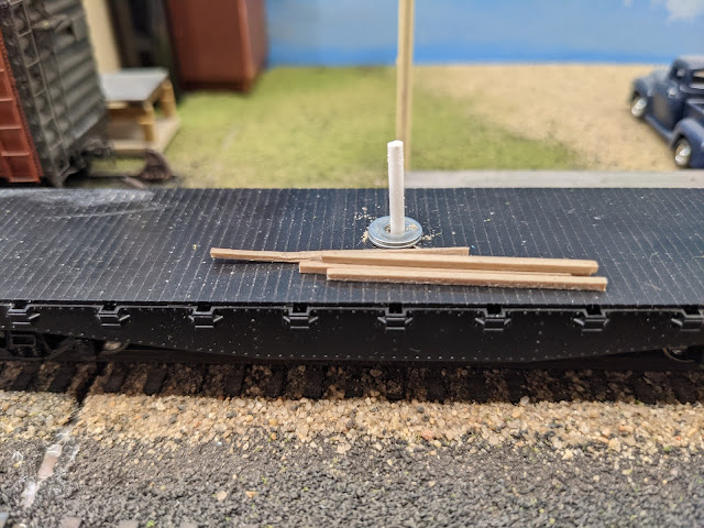
This is my 120' long test load for flatcars. It only took a few tries to get it to work. The piece is 1" x 1/4" basswood. I ran it a couple of times to see where I wanted it to sit, then I drilled holes in the flatcar decks and inserted a .06 styrene rod with about  3/8" sticking out. I then drilled the 2 holes in the piece of wood and gave it a test run. It crashed on the first 36" curve it came to so I added washers between the wood and the cars on the pins to raise it up so it cleared the deck of the middle car. I ran it again and it still crashed on the curve. I made the hole in the wood a little bigger and it made it through the first curve and crashed on the 2nd 30" tighter curve. I noticed at this point that the couplers on the cars were binding causing the cars to come off the track and tip over. I also noticed that there was no slack in the couplers. So I measured the amount of slack between a set of couplers. So to fix this I put the wood in my lathe and milled a slot extending from the holes to the middle of the car plus an extra .01" long. This allows the cars to have all the slack between the couplers. You would just make the slot longer if you had another idler car. 

This shows the milled slot in the load

I ran it again and it went all the way around on the main line with no problems. Next trial was in the yard and it ran with no problems on the ladders or any of the other tracks. The tightest curve I have is 24" and it also ran through that. The wood never tips over and rides very well. With the 1/4" thick wood it just come to the edge of center flat car which is only 9' wide. In order to have the same over hang as my passenger cars I can maybe go to to a load that  is 3/4" wide. The next step is to make a real load and the supports to support the load with the slots milled in them. The hole in the wood and the slots will only need to be .080 for it to work. The pins only extend through the plastic deck and can be removed so you are only left with a .06" hole.  This can be easily disguised if you are going to use the cars for other loads.

This picture shows the pins in the flat car deck and washers.