Showing posts with label Freight Cars. Show all posts

Wednesday, 10 April 2024

Resin kit learnings


Resin Kit Learnings

I have built a few of these kits and used resin detailed parts that I have cast or bought. I find these equally as challenging as any scratch built projects I have completed. There are some beautiful kits out there. I recommend that you start by buying one of these at a swap meet and put it together it will increase your modeling skill and problem solving. If you are not happy then you buy another and learn from that. These skills will build your confidence for when you want to scratch build an item.

 As some of you may know there can be some special challenges that are unique to resin. There are different types of resin you may want to know about.  I will go over how to to fix some problems that may come up with kit parts. I will cover the different types of glues that can be used. There are also steps to prep the resin for painting and additional things that have to be done when painting. 

Resin kits are created because they are cheaper to produce.  They do not require the expensive molds that are needed for injection molding and they can be produced in smaller runs. A lot of these kits would never be produced as injection molded kits. So they are special in this way. As with ALL kits it is very important to read all the instruction carefully then read all the instruction carefully again. You need to handle the parts with more care than injected molded kits as the parts can be brittle and will break if too much force is applied. Resin is easy to file, drill and even tap. They will also be covered in mold release which is used so the rubber molds do not get damaged when removing parts. This extends the life of the rubber molds. I will cover mold release later. 

The more modern kits use what we will call white resin, while some of the older kits were made using a yellow resin that is more brittle and harder to work with. If you are just starting out I would stay away from the yellow ones unless you get them really cheap and use them to learn on but maybe not keep in the end.

You will also may come across parts that have weak spots caused by air bubbles or are slightly warped and have flash that need to be removed. The directions will  instruct you on how to handle this. The parts need to be checked for flash and this can be filed away. When you come across a part that has a thin spot on the back that looks almost opaque or is a hole this doesn't mean the part can't be used. I use autobody filler to fill and reinforce these spots just gently apply it so you do not push it through to the front. Let it dry and sand it smooth. If you come across a part that is warped which usually happens on larger parts like walls or longer pieces then this can be fixed by using a hair dryer or a heat gun. You need a perfectly flat surface to lay the part on.  I use the glass that is on the top of my bench. Lay the part on the glass and evenly heat it with the hairdryer. As it gets hotter it will start to lay flat. Once you think it is flat place something on top of it to hold it down while it cools. This will work about 90% of the time. If it is a thicker part or it is being stubborn I will use the heat gun. You can also place the part in water that is 100C for 2-3 min. Then take it out and lay it flat. Once it has cooled it should hold it's shape. Of course that is not a hundred percent foolproof  as you can see below.  I bought this car  at a swap meet. Then the roof bent up in the middle. It had been heated 3 times both the frame and the roof. I was keeping it just as reference to scratch build a new one someday. 


It is now in the garbage some things just can't be fixed. This rarely happens so do not let it stop you from buying any of the resin kits that are out there.

Here is a picture of a Sylvan CN caboose model built from a kit that some have thought was a brass model. That was an oh baby I got it moment. The one stack has a small tilt from handeling


Mold release is like spraying Pam or silicone on your hands.  It will impede your glueing and painting so you must wash the parts first to remove the mold release.  This is a process you should be doing with all your kits no matter what they are made from. You can use  dish soap or  hand cleaner.  I use an old toothbrush to scrub it clean and then rinse it and allow it to air dry. 
For glueing you do not have many choices AC and epoxy glues are about the only ones that work reliably. AC is fast but epoxy is stronger.  

Now you have it put together and are ready to paint. You should, as with all projects inspect it for fingerprints and oil from your hands and spot clean those areas and let it dry. You just have to be careful with the details. You can chose the type of paint you want to use. I have used acrylic, lacquer and enamel based paints from different companies and all work well.

   Have Fun


Saturday, 21 January 2023

Scratch Built Car models part 2


This is a  models of a  CN Boom Aux. car to go with my crane. 

This picture looks in from one side of the car. That is a bunk bed, pail with real coal and the stove.

This look in from the other side showing cables and chain on the walls. Tools in the corner, a desk with paper work and a pinup poster above the desk. There are safety signs on both doors. The floor of the whole car is done with a wood plank texture scaled and printed on paper. The hardest part of this is finding the right texture and getting scaled to size. All the details on the deck are scratch built. The tool box hides the crew for the coupler. The cable is just coloured thread

This shows the stove and coal pail. The stove has a lever on the door and a lever on the dampener. I made the stove on my lathe and added legs to it. The sides fit into the stake pockets so they can move a bit and may look crooked but they can also be removed.

                           
You can see the caboose truck under the bunk end 

This shows the underside and all the bracking and piping. There is lead between the 2 center siles for weight. The floor on this side is scribed styrene.

This shows the inside of the roof with a plywood texture added to it.


CN Boom Car


1. Construction

The car was built from my own scale CAD drawings and some parts were cut out on a laser. The entire car was scratch built except for the purchased parts. The walls for the cabin, end sill, and bolster were cut on the laser. This car also has an interior. It follows the pictures of prototype cars but not exactly as I took certain features that I liked from different cars.


2. Detail

I used semi scale couplers and wheel sets. air hoses, brake system, fish belly under frame. The interior has tools, bunk bed, desk, stove, pin up girl on the wall, safety warnings signs, notes and instructions on the wall and chains. I have added blocking, spreader bars, cable, tool box, pieces of rail to the deck. The under frame has braking and all the bracing. There is a kick plate on the bottom of the door front door.

3. Conformity

The building of this car closely follow but not exactly the CN type car that was built from a converted flatcar from CN. I did not have diagrams of the under frame or the interior. The car has a fish belly under frame. The sides of the cabin have 3.5 in vertically spaced boards on the walls and ends. The floor is 5in boards on the inside and out. The brake system is AB with a rising stem brake wheel. The exterior colours and lettering are correct for CN car pre 1959. The roof and the top of the end walls are plywood. It has a wood roof walk. The trucks are Bentendorf on one end and caboose truck under the cabinThere are no boards going up to the roof walkway in the pictures I had.

4.Finish

The top of the floor, and interior of the roof are finished with scaled and printed wood textures on paper. The inside of the roof is plywood texture. The floor is 6" boards. These textures are scaled then cut out and glued to the styrene roof and floor. The interior of the car is then weathered. The exterior and underside of the floor is scribed styrene. The car was air brushed a CN red #11 and weather with chalks. The lettering is a custom decal set I had made.

5.Scratch Building

The car is scratch built from my own CAD drawings with the exception of brake parts, trucks, wheels, coupler and box. The walls, roof, frame, bolsters were built from plain or scribed styrene. There is lead added between the fish belly sills to give weight. The spreader bars, deck boxes, stove, doors are also scratch built. The low sides are built using board by board.

Commercial Parts

-Tichy AB brake parts, grab irons and stake pockets

-Tichy grab irons

-Kadee air hoses, semi scale couplers, coupler pockets and 088 wheel sets

-Accurail Andrews trucks

-Trueline CN #11 red paint

-Custom made decals

-scale chain

-weathering chalks

Building Materials

-.04 scribed and plain styrene sheet

-.06 plain styrene sheet

-.005 clear sheet

-styrene 1x2, 1x4, 1x6, 2x2, 2x4,2x6, 2x8, 4x4, 4x6

-styrene round rod

-lead sheet .02

-cut wood for blocking


CN/GTP Horse Car

 CN168108 Horse Car

It is the oldest built car I have on my layout it was GTP in 5/1889


1. Construction

This car was built from Cad drawings that I made from some pictures I have of this car and data from Ian Cranston's Canadian Freight Cars site. Styrene was used for just about all the construction. My main concern during this build was that this car would run properly as it will be a working car on my layout. Some parts were cut on the laser and lathe.


2. Detail

All the brake piping and parts have been added. The roof vents. The top boards on the wall. Trim around the small vents. Roof grabs. Custom decals. Cut levers. Queen posts are made from stick pins and .015 wire for the tension rods. I had queen posts but could not find them until I was done!!! Water tanks. Air hoses. Screen on doors, end doors and vents. Supports for roof walk, stalls, straw, feed and feed containers for the horses I know the cross brasses are not like the ones pictured because I could not make them work and have dependable support for the car due to the delicate nature of the parts that would have been required. So the design was changed. All the doors are glued on with tacky glue so the doors can be positioned open or closed.

3. Conformity

The building of this car closely follows the pictures of the proto type but not exactly. Some data was used from other types of horse cars. The car was built for GTP in 5/1889The car was rebuilt 1930 then renumbered in the series 168100-168122. These cars were retired between 1961 and 1966. It received an all steel under frame in 1930I did not have diagrams of the under frame or the interior. This car is IL 48’, IW 9’, IH 7’8”. The car has a fish belly under frame. The sides have 3.5 in vertically spaced boards on the walls and ends. The floor is 5in boards on the inside and out. The brake system is AB with a rising stem brake wheel. The exterior colours and lettering are correct for CN freight car per 1959The roof and the top of the end walls are plywood. It has a wood roof walk. The trucks are BentendorfThere is 1x4 strip added on the top of the sides and ends and metal on the corners where the ends and sides meet. It has 18”grabs, cut levers and roof vents. This car has no boards from car edge to walkway, when this car was built plywood was not yet standardized to 4’x 8’ sheets. The stalls are built to a common design that could be folded up on the inside of the car.

4.Finish

The floor, is finished with scaled and printed wood texture. These texture is cut out and glued to the styrene floor. The interior of the car is then weathered. The car was air brushed a CN red #11 and weather with chalks. The decals for this car were custom made. Straw has been add to the floor and a pile of feed for horses. Screen was added to the small vents, doors and end door opening using used plastic tea bag material.

5.Scratch Building

The entire car is scratch built with the exception of brake parts, trucks, wheels, coupler and box. The walls, roof, frame, bolsters and stalls were built from styrene. I drew the car in CAD. There is lead added between the sides of the fish belly frame to give weight. The walls, doors, centre sill, bolsters and braces are laser cut. The water tanks under the floor and the roof vents I made on my lathe. The wall and door board lines were rastered on both sides of plain styrene sheet, then the parts were cutout. The centre sill is laminated together with a layer of styrene on the outside and pieces of lead sheet in between to add weight to the car, then a trim was added to the bottom. The slots and holes for the brake lines were drilled and then used my Dremel to mill the slots. The bolsters were laminated together and drilled and tapped. The coupler boxes were placed and the floor was drilled and tapped for a 2-56 screw. This way they can be removed to replace springs if needed. The roof interior braces were laser cut. The roof was built and the braces in stalled. I manged to cut the walkway supports with the lathe, they are so tiny. These were glued on to the roof then 1x6 boards were glued to them. Due to the delicate nature nail holes were not applied. The trim around the small top vents was also laser cut. Door tracks, handles, supports, and small parts were added.

The 2 larger vessels are the water tanks


This shows the inside of the roof and the roof brackets that hold the roof panels and slides in against the walls


        Here is a picture with it loaded with horses. The stalls are made from styrene strip


The doors are held on with tacky clue so they can be put in the open position if I want. The window screen on the doors is from nylon tea bags. It is an old car at this point and is weather acordingly. The decals are custom made, it has a pylwood roof and was built before plywood came in 4x8ft sheets.


Materials Used

Evergreen

-.06 plain sheet

-.04 styrene .03 grooved

-.04 plain styrene sheet

-.02 plain styrene sheet

-.01 plain styrene sheet

-.005 clear styrene sheet

-.02, .04 styrene rod

-.06 styrene tube

-.04 half round styrene

-1x2,1x3, 1x4, 1x6, 1x8, 2x4, 2x6, 2x8, 2x10, 2x12, 4x4, 4x6 6x8, 8x10 styrene

-.02 lead sheet

-.012 music wire

-.016 music wire

-straight pins

-1/8”, 1/4” wood dowel

-printed wood texture

-used tea bags for screen


Purchased Parts

-Accurail trucks

-Tichy AB brake parts

-Tichy 18” grabs

-Tichy stirrups

-Kadee air hoses

-Kadee semi scale couplers and boxes

-Kadee semi scale wheels


Monday, 22 March 2021

120' Flat Car Load


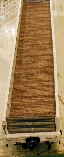
This is my 120' long test load for flatcars. It only took a few tries to get it to work. The piece is 1" x 1/4" basswood. I ran it a couple of times to see where I wanted it to sit, then I drilled holes in the flatcar decks and inserted a .06 styrene rod with about  3/8" sticking out. I then drilled the 2 holes in the piece of wood and gave it a test run. It crashed on the first 36" curve it came to so I added washers between the wood and the cars on the pins to raise it up so it cleared the deck of the middle car. I ran it again and it still crashed on the curve. I made the hole in the wood a little bigger and it made it through the first curve and crashed on the 2nd 30" tighter curve. I noticed at this point that the couplers on the cars were binding causing the cars to come off the track and tip over. I also noticed that there was no slack in the couplers. So I measured the amount of slack between a set of couplers. So to fix this I put the wood in my lathe and milled a slot extending from the holes to the middle of the car plus an extra .01" long. This allows the cars to have all the slack between the couplers. You would just make the slot longer if you had another idler car. 

This shows the milled slot in the load

I ran it again and it went all the way around on the main line with no problems. Next trial was in the yard and it ran with no problems on the ladders or any of the other tracks. The tightest curve I have is 24" and it also ran through that. The wood never tips over and rides very well. With the 1/4" thick wood it just come to the edge of center flat car which is only 9' wide. In order to have the same over hang as my passenger cars I can maybe go to to a load that  is 3/4" wide. The next step is to make a real load and the supports to support the load with the slots milled in them. The hole in the wood and the slots will only need to be .080 for it to work. The pins only extend through the plastic deck and can be removed so you are only left with a .06" hole.  This can be easily disguised if you are going to use the cars for other loads.

This picture shows the pins in the flat car deck and washers.


Wednesday, 8 July 2020

Scratch Built Car models part 1

Here are 2 of the 4 cars that I built. I will show the other 2 cars in my next post. These 4 cars are all scratch built and I have included the description. I started these 4 cars in Jan 2020 and finished these 2 by April. I had no drawings for the gondola only one picture and only two pictures and a very simple drawing for the Express car. All the decals on the cars were made by William Brillinger from Precision Design Co in Altona Manitoba billy@pdc.ca  He is a really great guy to work with. You may also want to have a look at my post of  How I Build my Scratch Projects and Using Textures and Pictures. The floors on these cars have textured flooring added to them. I would never be able to paint them to make them look this good. When I print them I do it in draft as it gives them a duller look and they blend in better. You can weather them a bit with chalks and not loose any of the detail.

For the next cars that I am going to build I will get .04" steel laser cut with the hole for the coupler screw cut in at the same time. I think I will get the board lines on the bottom rastered in and this will take car of the weight problems when building from just styrene. I am considering having the bolsters and center sill cut out of metal as they would be easy enough to solder on. 

CNR 8903 Express Car

The grey you see in the center sill is the sheet lead. The holes for the bolsters and couplers have been drilled and tapped. At this point the trucks were put on and I gave them a test run.


You can see the tabs on the side where the floor goes through the doorway and how much curve is in the ends

It has all the cross members along with all the braking installed

Walls and ends have been glued on and the roof fitted on. It is about to get another test run.

In the paint booth

Just finished painting

The horses have all been hand painted. You can see the last set of panels piled against the wall when  they are not used. I also made some feed pails. I used real ground up straw on the floor.


You can see the roof vents, rain guards and ladder supports that were added to the roof.

In this view you can see the 2 water tanks, the generator and the battery box

This shows the B end

Here is the description that accompanied this model for judging

CN8903 78’ Express Horse Car


1. Construction

I used pictures and a partial drawing that is in CNR Vol 2 An Annotated Historical Roster Of Passenger Equipment by Guy Lepkey. I drew this car in CAD and then worked from those drawings. The walls, ends and doors are laser cut. This car is built to be run on my layout. This car was constructed out of styrene. The walls, ends and doors are laser cut. These parts were cut from scribed styrene. The coupler boxes are drilled, taped and screwed to the car so they car be removed to fix things like coupler springs. The trucks are also screwed to the bolsters which have also been drilled and taped. The center sill has lead laminated along with styrene for weight and to keep the center of gravity low in the car. Once this was done the car was test run and it ran very nicely. The floor is scribed on the bottom and all the parts added to it. The wood texture was then glued to the floor. Then the texture was cut and glued to walls and ends and then the walls and ends were glued in place. Next the roof had some adjustments made to it so it could be removed and support the walls. Simulated tare paper was then added to the roof along with the vents and rain drip strips above the door openings. Once this was done the grab irons, brake lever, stalls end door were added. The car was then painted as outlined below. The diaphragms were then added along with the lettering. You may see a gap between the roof and the wall in the middle. This is a result of the roof having a natural curve to the plastic that I could not get completely straight. If I glue it down there would be no space and I will most likely do this for normal operation because of the chance of the roof coming off when someone is trying to re-rail the car.

2. Detail

Once the walls were cut out, the half round edge trim was added to the door opening edges. Braking with all the piping. There are 2 water tanks with piping that have been installed. A generator and battery box have been added. There are double walls on the ends. Scaled board texture was added to the interior of the walls and floor. There are air, signal and steam lines with hoses. Windows in the doors have different styles so this is the one I picked. The grabs were added as per photos. The brake adjuster on the B end is a lever operated as per photos. The end wall is curved side to side and curved to fit the roof. Vents, drip lines and ladder grabs were added to the roof. I added some feed and water containers. Real ground straw was added. I never knew that the end walls were curved side to side and that there was a double wall on express cars. Horses were hand painted and added. The panels at the end of the car are standing against the wall which is where they would be placed if the car was used as a baggage car. A worker was also placed.

3. Conformity

This was a GTR are in the series 1200-1209 blt 5/23 then became CN 8900-8909 and was retired in 9/61. This car hauled race horses and could hold up to 24. The building of this car closely follows the prototype but is not exact due to a lack of data. The sides have 3.5 in vertically spaced boards on the walls and ends inside and out. The floor is 5in boards on the inside and out. The brake system is a modified AB system referred to as UC type that has the 2 extra air reservoirs. I used a diagram of this brake system that is in CNR Vol 2 An Annotated Historical Roster Of Passenger Equipment by Guy Lepkey. The car is 10’ wide and has a fish belly under-frame. The smaller doors are 5’ wide and the centre opening is 7’ wide using double doors. Car end diaphragms have been added. There are double end walls. The outside end wall is curved to fit the roof and curved from side to side. There are doors in the car ends, although they would not be used if horses were present. The exterior colours and lettering are correct for CN passenger cars prior to 1954 and was never updated. This car is only 2 years away from retirement. The stalls are a common design so they can be folded up to hang on the walls.

4.Finish

The floor and interior walls are finished with scaled and printed wood textures. These textures are then cut out and glued to the styrene walls and floor. The interior of the car is then weathered. The clerestory roof has been scribed and painted with a brush to give the look of tar paper. The floor on the underside was air brushed a flat black and weathered with chalks. The sides and ends are painted CN green #11 and also weathered. The decals are what was on the car in 1959 and show some weathering.

5.Scratch Building

I scratch built this car except for the roof. The clerestory roof had to be adapted to work with the walls. The walls, frame, bolsters, battery box and stalls were built from styrene. I drew the car in CAD. There is lead added between the sides of the fish belly frame to give weight. The walls, doors, centre sill parts, bolsters and braces are laser cut. The ends had to be cut with a curve to match the clerestory roof line. The water tanks and generator under the floor were made on my lathe. The door board lines were rastered on both sides of a plain styrene sheet, then the parts were cut-out. The centre sill is laminated together with a layer of styrene on the outside and pieces of lead sheet in between to add weight to the car, then a trim was added to the bottom. The slots and holes for the brake lines were drilled and then I used my Dremel to mill the slots. The bolsters were laminated together and drilled and tapped. The coupler boxes were placed and the floor was drilled and tapped for a 2-56 screw to mount them. This way they can be removed to replace springs if needed. The stalls are built from 2x3 strip. I made some feed containers, used real ground straw. All the grabs were scratch built except for the ladder rest on the roof. I built a gig to bend the grabs. The brake adjuster on the B end was also scratch built. Glass was added to the door windows. There was also vents added to the roof.

Materials Used

Evergreen

-.06 plain styrene sheet

-.04 plain styrene sheet

-.02 plain styrene sheet

-.01 plain styrene sheet

-.001 clear styrene sheet

-.04 scribed styrene sheet

-.02, .04 .06 rod

-.04 tube

-.04 half round

-1x2,1x3, 1x4, 1x6, 1x8, 2x2, 2x4, 2x6, 2x8, 2x10, 2x12, 4x4, 4x6, 6x6, 8x8, 8x10

Other

-.02 sheet lead

-1/8”, 1/4” , 5/16 dowel

-.012 music wire

-.023 music wire

-straw

Purchased Parts

-Tichy AB brake parts

-3axel passenger trucks

-Kadee semi scale couplers and boxes

-Kadee air hoses

-A-Line diaphragms

-2/56 screws for trucks and couplers

-Walthers Clerestory roof

-horses

-CN Lines decals

-CN #11 green

-weathering chalks

-3 or 4 other paint colours


CN 65' Gondola


With the floor complete I put the trucks on and gave it a test run


Shows the scaled texture glued to the floor

The sides, end buffer, grabs, steps, tiedowns, and cut lever have been assembled. I am also test fitting the ends that had to be shortened and one rib removed from the top of the Tichy end. 

It is ready to go to the paint shop

This shows the 7/8" rivet decals from Archer. They can be a little testy to put on because they have to be cut so thin that the carrier is then weak and so they will break into small pieces. A narrow coloured strip form Microscale would not have this problem as the paint helps to hold it together. It took about 1-1.5 hrs per side and is still easier than punching them in.


The bolts/rivets on the head on the vessel are white glue put on with the end of a pin. Once they are dry you can't see them until you paint.

This picture shows an over length pipe load that will require that a flat car. Each pipe has been filled with sand to give weight to the car.


The ends had to be cut in height and width. This also shows the wood plank texture on the floor. I may go back and see if I can make the seam on the end disappear however, I am also zoomed in very close in the picture-this is not seen with the naked eye.


Because this car is a little light I made these scrap loads for when it is running empty. Each weight is one ounce.

CNR 65’ Gondola

1. Construction

This car was built from Cad drawings that I made from a picture seen in Canadian National Colour Guide To Freight and Passenger Equipment. Styrene was used for just about all the construction. My main concern during this build was that this car would run properly as it will be a working car on my layout. Some parts were cut on the laser and lathe. I also built loads for this car from scratch.


2. Detail

This car was built in 1958 and was in service in 1959 on my layout. The underside is very detailed with brakes and bracing. The box that is part of the decaling is used to show that it has a nailable floor. The drop ends are removable. Tie downs were added to the inside of the sides. There 7/8” rivets added to the sides on the bottom and at floor level on the outside they are very small. Scratch built loads.

3. Conformity

The building of this car closely follows the pictures but is not exact. The drop ends can be removed. This car is IL 65’, IW 7’9” as per the design to accommodate tight trackage and has an IH 3’6

4.Finish

The floor is finished with scaled and printed wood texture that  is cut out and glued to the styrene floor. The rivet decals were installed before the car was painted. The car was airbrushed a CN red #11 and weathered with chalks. The decals for this car were custom made.

5.Scratch Building

The entire car is scratch built with the exception of the brake parts, trucks, wheels, coupler and box. The ends have been heavily modified to width and height. The sides were cut from .02 plain styrene, bolsters were cut from .06 styrene and laminated together and drilled and tapped. The floor was cut from .04  and was scribed at .06 with scaled wood texture glued to the top. The side supports are cut from 4x4 with a .06 trim on the end. The underside has braces and AB brakes. I have built 3 loads for this car. The vessel was built on my lathe and before glueing it together it was filled with sand for weight. The sand load has a magnet installed along with some weight. It has 1/8 hardboard with sand glued on top. The 75’ pipe load was made with plastic drinking straws that were filled with sand for weight. There are also 2 weights made to look like scrap for when the car is empty.

Materials Used

Evergreen

-.04 styrene .06 grooved

-.04 plain styrene sheet

-.02 plain styrene sheet

-.01 plain styrene sheet

-.08x.08 for bracing

-.02, .04 rod

-1/2” tube

-1/4” plastic straw

-1/4”, 1/2” wood dowel

-1x2,1x3, 1x4, 1x6, 1x8, 2x2, 2x4, 2x6, 2x8, 2x10, 2x12 4x4, 4x6, 8x8, 10x12

-sand

-various sized wood

-wire of various size

Purchased Items

-Accurail Bettendorf trucks

-Tichy gondola ends

-Tichy AB brake parts

-Tichy 18” grabs

-Tichy stirrups

-Kadee air hoses

-Kadee semi scale couplers and boxes

-Kadee semi scale wheels

-Archer rivet decals

-Details West lift rings


Friday, 25 October 2019

CN Lime Stone Hoppers and Loads


I had a need for another train that didn't interchange cars and is just a through train. This helps to keep the amount of work for the yard crew manageable. I received information from Graham Wood as he was engineer on this particular train that ran between Hudson Bay, Sk and Regina, Sk. The lime stone was used in a cement plant east of Regina.


Here are the Accurail hoppers that I found at Walthers on a sale deal. I had another 3 cars that I had picked up at a swap meet that are not in the picture. I have space to run a 13 car train.

 I used my Badger air eraser to remove the lettering off the cars. I do not have pictures of these cars but I have pictures below of other cars I have done. I use baking soda instead of silica in my eraser. It is not harsh or dangerous to the respiratory system. Charlie and I had built a booth that is sealed that I use with the eraser.  The finish from this process is very smooth so re-painting is not a problem. To do either one of the cars below took about 10 min. 


The picture below shows the cars after they have been painted CN red #11. The Kadee #58 couplers have been re-installed. I  cut off the trip pins on all my cars as I have no need for them. All cars get a pair of Kadee air hoses. I could have painted them with the couplers on if I had wanted to as I have a piece of shrink tube that I cut off and slide over the coupler to keep them safe from paint. I chose not to do some of the modifications that were outlined by Stafford Swain's article on hopper cars.

I had custom decals made for these cars  by William Bellandger from Manitoba. The good part of having the decals made was I could change the size of the CANADIAN NATIONAL, built dates, re-weights, coal and stone levels and car number and data that was unique to each car. This made decaling the cars very easy. Took a little more time to set it up and check that they were correct before they were printed. As a result it only took about 15 min to decal the side and one end of a car because of the work done above. The cars were then weathered inside and out with chalks and then a shot of acrylic dull coat. The trucks were reinstalled with new code 88 metal wheel sets. 

Below are pictures for the loads. I ripped 1/8" hard board through my band saw and then cut them to length and trimmed the corners to fit the hoppers. Each piece was test fitted inside a car to ensure that it would go in and out without sticking. I then glued on 1/4" super magnets in the center. They are only an 1/8" high so they are easy to cover. They are laying on my garage floor in the sun letting the glue set.


I then laid down a garbage bag on the floor and painted all the load boards and magnets black. Just using a can of flat black paint.


Here you can see the lime stone glued to the board. I took real lime stone and put it in a bag and smashed it with a 4 lb hammer  to crush it down to size. The size of the crushed lime stone was up for debate but it looks good at the size it is. I then screened it. I had to pick out some of the larger pieces because I didn't have a screen size that would work. Still on the garage floor I poured the crushed stone on to the boards until I was happy with the load shape. I didn't worry if stone was on the sides of the loads, as I had done a test with my coal loads and found it is easy to break off anything that gets stuck to the side. I then sprayed them with water with a little alcohol in it and then used diluted white glue to glue everything down and left them again in the sun to dry. Once they were dry I broke off the stray pieces from the sides and then sprayed all the loads with a dull coat. To remove the loads from the cars I use one of the extra magnetic wands that I have from Rapido passenger cars. I used the same process to build my coal loads by just substituting stone for real coal.

Here are some pictures of the cars. Normal power for this train for now is 2 GMD1's and 1 GP7. This train leaves from Regina and goes on the Qu'Appelle sub to Melville and then on the Yorkton sub to Yorkton and on to Hudson Bay where it gets loaded and then returns back to Regina and is then interchanged out to the cement plant east of the city.


Below are pictures of the train.